 5ThePeranceofFeedbackControlSystems反馈控制系统的性能课件

《5ThePeranceofFeedbackControlSystems反馈控制系统的性能课件》由会员分享,可在线阅读,更多相关《5ThePeranceofFeedbackControlSystems反馈控制系统的性能课件(52页珍藏版)》请在装配图网上搜索。
1、,,,单击此处编辑母版标题样式,单击此处编辑母版文本样式,第二级,第三级,第四级,第五级,,,*,,,,,单击此处编辑母版标题样式,单击此处编辑母版文本样式,第二级,第三级,第四级,第五级,,,*,,,,单击此处编辑母版标题样式,单击此处编辑母版文本样式,第二级,第三级,第四级,第五级,*,,*,,,,,,单击此处编辑母版标题样式,单击此处编辑母版文本样式,第二级,第三级,第四级,第五级,,,*,,,,单击此处编辑母版标题样式,单击此处编辑母版文本样式,第二级,第三级,第四级,第五级,,,*,单击此处编辑母版标题样式,单击此处编辑母版文本样式,第二级,第三级,第四级,第五级,,,*,,,,单击
2、此处编辑母版标题样式,单击此处编辑母版文本样式,第二级,第三级,第四级,第五级,,,*,单击此处编辑母版标题样式,单击此处编辑母版文本样式,第二级,第三级,第四级,第五级,,,*,,,,,,单击此处编辑母版标题样式,单击此处编辑母版文本样式,第二级,第三级,第四级,第五级,,,*,,,,单击此处编辑母版标题样式,单击此处编辑母版文本样式,第二级,第三级,第四级,第五级,,,*,,,,单击此处编辑母版标题样式,单击此处编辑母版文本样式,第二级,第三级,第四级,第五级,,,*,,,,单击此处编辑母版标题样式,单击此处编辑母版文本样式,第二级,第三级,第四级,第五级,,,*,,,,单击此处编辑母版标
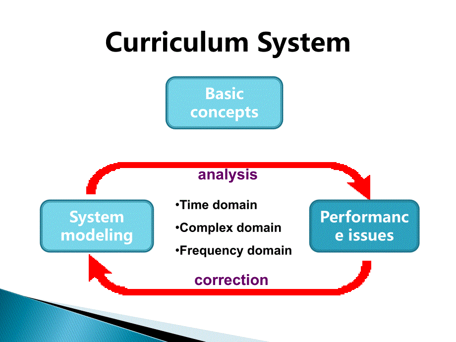
3、题样式,单击此处编辑母版文本样式,第二级,第三级,第四级,第五级,,,*,,,,单击此处编辑母版标题样式,单击此处编辑母版文本样式,第二级,第三级,第四级,第五级,,,*,Curriculum System,Basic concepts,System modeling,Performance issues,analysis,correction,Time domain,Complex domain,Frequency domain,Curriculum SystemBasic concept,Chapter 5,,The Performance of Feedback Control Syst
4、ems,Test Input Signals,Performance of Second-Order Systems,The s-Plane Root Location and the Transient Response,The Steady-State Error of Feedback Control Systems,Effects of a Third Pole and a Zero on the Second-Order System Response,Performance Indices,Design Examples,-Specify the measures of perfo
5、rmance,Chapter 5 The Performance of,Define and measure the performance of control systems,Stability,Transient response,:,the response that disappears with time,Steady-state response: the response that exists for a long time following an input signal initiation,Design specifications: for a specified
6、 input command,Time response indices,Desired steady-state accuracy,Effective compromise,5.1 Introduction,Define and measure the perform,Step input,Ramp input,Parabolic input,,5.2 Test Input Signals,Step input5.2 Test Input Sig,Unit impulse,,The unit impulse function,δ,(t),has the following pro
7、perties:,,The impulse input is useful when we consider the convolution integral for the output,y(t),in terms of an input,r(t),,which is written as,,,The general form of standard test signals:,,,5.2 Test Input Signals,Unit impulse5.2 Test Input S,If the input is a unit impulse function, we have,,
8、The integral has a value only at,τ,= 0; therefore,,,the impulse response of the system G(s).,The impulse response test signal can often be used for a dynamic system by subjecting the system to a large-amplitude, narrow width pulse of area A.,The standard test signals are of the general form and the
9、Laplace transform,,,5.2 Test Input Signals,If the input is a unit impulse,5.2 Test Input Signals,5.2 Test Input Signals,With a unit step input,5.3,Performance of a Second-order System,With a unit step input5.3 Pe,The response as a function of,ζ,and time is also,shown in Figure 5.5(b) for a s
10、tep input.,As,ζ,decreases, the closed-loop roots approach the imaginary axis, and the response becomes increas-ingly oscillatory.,5.3,Performance of a Second-order System,The response as a function,With an impulse function input R(s)=1,5.3,Performance of a Second-order System,With an impulse functio
11、n input,The swiftness of the response is measured by,the rise time,T,r,,and,the peak time,T,p,.,For under-damped systems with an overshoot, the 0-100% rise time,T,r,,is a useful index.,If the system is over-damped, then the peak time is not defined, and the 10-90% rise time,T,r1,,is normally used.,T
12、he actual response matching the step input is measured by the,percent overshoot,and,settling time,Ts,.,The percent overshoot is defined as,,,where,Mpt,,,is the peak value of the time response, and,fv,is the final value of the response.,,,Standard performance measures,5.3,Performance of a Second-orde
13、r System,The swiftness of the response,The settling time,,Ts,, is defined as the time required for the system to settle within a certain percentage,δ,of the input amplitude.,For the second-order system with closed-loop damping constant,ζω,„,,Ts,for which the response remains within 2% of the final v
14、alue is,Hence, we will define the settling time as four time constants (that is,,r = l/,ζω,„,),of the dominant roots of the characteristic equation.,5.3,Performance of a Second-order System,The settling time, Ts, is defi,Notice:,The transient response of the system may be described in terms of two f
15、actors:,The swiftness of response, as represented by the rise time and the peak time.,The closeness of the response to the desired response, as represented by the overshoot and settling time.,As nature would have it, these are contradictory requirements, and a compromise must be obtained.,5.3,Perfor
16、mance of a Second-order System,Notice:5.3 Performance of a,Let dy(t)/dt=0, we obtain,ω,n,β,t=,π,.,5.3,Performance of a Second-order System,Calculation of the measures,Let dy(t)/dt=0, we obtain ωnβt,5.3,Performance of a Second-order System,5.3 Performance of a Second-,T,r1,versus,ξ,5.3,Performanc
17、e of a Second-order System,Tr1 versus ξ5.3 Performa,When,ξ,is set to 0.2,When,ω,n,,is set to 5,For a given,ξ,, the response is faster for larger,ω,n,.,The overshoot is independent of,ω,n,.,For a given,ω,n,, the response is faster for lower,ξ,.,T,he swiftness of the response, however, will be l
18、imited by the overshoot that can be accepted.,5.3,Performance of a Second-order System,When ξ is set to 0.2When ωn is,5.4 Effects of a Third Pole and a Zero on the Second-order System Response,When |1/,γ,|≥10|,ζ,ω,n,|, the performance indices can be represented by the ones of the second order syst
19、em.,In the case, the poles of the second order system are called dominant poles of the system.,5.4 Effects of a Third Pole,Notice: the above results is only for a transfer function without finite zeros.,5.4 Effects of a Third Pole and a Zero on the Second-order System Response,Simulation results
20、 for,ζ,=0.45,Notice: the above results is o,5.4 Effects of a Third Pole and a Zero on the Second-order System Response,When the transfer function has a zero,,5.4 Effects of a Third Pole,5.4 Effects of a Third Pole and a Zero on the Second-order System Response,5.4 Effects of a Third Pole,Exa
21、mple 5.1,Parameter selection,For the given system, select the gain,K,and the parameter,p,so that the time-domain specifications will be satisfied.,P.O.≤5%,Ts ≤4s,ζ,=0.707, P.O.=4.3%,Ts=4/,ζω,n,≤4,,ζω,n,≥1,Chose r12=-1±j, then P.O.=4.3% Ts=4s,ζ,=0.707,,ω,n,=1/,ζ,=1.414,5.4 Effects of a Third Pole a
22、nd a Zero on the Second-order System Response,Example 5.1 Parameter select,Example 5.2,Dominant poles of T(s),If a>>,ζω,n,and,τ,<< 1/,ζω,n,, the pole and zero will have little effect on the step response.,P.O.=55% according to Fig 5.13(a),Ts=4/3=1.33s,5.4 Effects of a Third Pole and a Zero on th
23、e Second-order System Response,Using a computer simulation for the actual third-order system, we find that the percent overshoot is,equal to 38% and the settling time is 1.6 seconds,. Thus, the effect of the,third pole of,T(s) is to dampen the overshoot and increase the settling time,(hence the real
24、 pole cannot be neglected).,Example 5.2 Dominant poles o,According to the percent overshoot P.O.,According to the number of cycles of the damped sinusoid during,Ts,5.5 Estimation of the Damping Ratio,The frequency of the damped sinusoidal term for,ζ,< 1 is,The number of cycles in 1 second is,ω,
25、/2,π,. The time constant for the exponential decay is,τ,=,l/,ζω,n,,in seconds. The number of cycles of the damped sinusoid during one time constant is,,Assuming that the response decays in,n,visible time constants.,,For the second-order system, the response remains within 2% of the steady-state valu
26、e after four time constants (4,τ,, i.e.,,n =,4),According to the percent over,Example: examine the response shown in Figure for,ζ,,= 0.4,.,,5.5 Estimation of the Damping Ratio,Use,y(t),= 0 as the first minimum point and count 1.4 cycles visible (until the response settles with 2% of the final val
27、ue). Then we estimate,Example: examine the response,5.6 The,S-plane Root Location and the Transient Response,5.6 The S-plane Root Location,Ea(s), actuating signal, which is a measure of the system error.,E(s)=R(s)-Y(s), the actual system error.,When H(s)=1,,5.7 The Steady-state Error of Feedback
28、 Control Systems,Ea(s), actuating signal, whic,N is call the type of systems.,N=0, type-0 system; N=1, type-1 system; N=2, type-2 system;,For a type-0 system,Define,as position error constant.,For N,≥1,5.7 The Steady-state Error of Feedback Control Systems,Step input,N is call the type of systems.
29、,For the system with N=0, the steady-state error is infinite.,For the type-1 system,,is defined as velocity error constant.,Thus the steady-state error exists.,For the type-2 system, the steady-state error is zero.,Ramp input,5.7 The Steady-state Error of Feedback Control Systems,For the system wit
30、h N=0, the s,For N=0 and 1, ess=,∞;,For N=2,Acceleration error constant,5.7 The Steady-state Error of Feedback Control Systems,Acceleration input,For N=0 and 1, ess=∞;Accelerat,For a step input,When K2=0,,When K2>0,For a ramp input,5.7 The Steady-state Error of Feedback Control Systems,Example 5.3
31、,Mobile robot steering control,,In the case of the steering control system, we want to increase the gain factor,KK2 in order to,increase,Kv and reduce the steady-state error. However, an increase in KK2 results,in an attendant decrease in the system's damping ratio,ζ,and therefore a more oscillatory
32、 response to a step input. Thus, we want a compromise that provides the largest,Kv based on the smallest,ζ,allowable.,e,ss,=0,For a step input For a ramp in,5.8 The Steady-state Error of of Nonunity Feedback Systems,A nonunity feedback system,A speed control system: K1 and K2 account for the conver
33、sion of one set of units to another set of units.,The equivalent block diagram with K1=K2.,A unity feedback system.,5.8 The Steady-state Error of,If K1=K2, the system is transformed to that of Fig 5.23 (for the dc gain or steady-state calculation) .,5.8 The Steady-state Error of of Nonunity Feedba
34、ck Systems,If K1=K2, the system is transf,Determine K1 and calculate the steady-state error for a unit step input.,Solution:,Select K1=K2=2,5.8 The Steady-state Error of of Nonunity Feedback Systems,Example 5.4,Steady-state error,or 5.9% of the magnitude of the step input.,Determine K1 and calculat
35、e the,Assume we cannot insert a gain K1 following R(s). The actual error is E(s)=[1(s)-T(s)]R(s).,Try to determine an appropriate gain K so that the steady-state error to a step input in minimized.,To achieve zero steady-state error, we require that,Thus K=4 will yield a zero steady-state error.,5.8
36、 The Steady-state Error of of Nonunity Feedback Systems,Example 5.5 Feedback System,Solution:,Assume we cannot insert a gain,A performance index is a quantitative measure of the performance of a system and is chosen so that emphasis is given to the important system specifications.,ISE:,IAE:,ITAE:,
37、ITSE:,,,,5.9 Performance Indices,The calculation of the integral squared error (ISE).,A performance index is a quant,For a step input,5.9 Performance Indices,Example 5.6,Performance criteria,The performance index ITAE provides the best selectivity of the performance indices.,The value of the d
38、amping ratio,ζ,selected on the basis of ITAE is 0.7. For a second-order system, this results in a swift response to a step with a 4.6% overshoot.,For a step input5.9 Perform,Select,K,3,to minimize the effect of the disturbance D(s).,5.9 Performance Indices,Example 5.7,Space telescope control s
39、ystem,Select K3 to minimize the effe,With,K,1,=0.5,,K,1,K,2,K,p,=2.5 and a unit step disturbance,5.9 Performance Indices,Then the natural frequency of the vehicle is,K,3,= 3.2 and,ζ,= 0.5,. (ISE),K,3,= 4.2 and,ζ,= 0.665,. (IAE),With K1=0.5, K1K2Kp=2.5 and a,Complex systems with high-order transfe
40、r functions,,lower-order approximate model,Method 1: delete a certain insignificant pole, in the meanwhile retain the steady-state response.,,Example:,,5.10 The Simplification of Linear Systems,Complex systems with high-orde,- Method 2: frequency response methods,Criteria: Select c,i,and d,i,in su
41、ch a way that L(s) has a frequency,response very close to that of H(s),q=1,2,,……,,5.10 The Simplification of Linear Systems,in which the poles are in the left-hand s-plane and m <,n.,where,p ≤ g < n, K without change.,- Method 2: frequency response,Example 5.9,A simplified model,5.10 The Simplif
42、ication of Linear Systems,Example 5.9 A simplified mo,Poles: S=-1, -2, -3,→→→,-1.029, -1.555,5.10 The Simplification of Linear Systems,Poles: S=-1, -2, -3 →→→ -1.,Choose K and K1 so that:,(1) The percent overshoot of the output to a step command r(t),≤10%;,(2) The steady-state error to a ra
43、mp command is minimized;,(3) The effect of a step disturbance is reduced.,5.11 Design Example: Hubble Telescope Pointing Control,Choose K and K1 so that:5.11,(1) Select K and K1 to meet P.O.,≤10% for R(s)=A/s. Set D(s)=0.,When,ζ,=0.6, P.O.=9.5%.,5.11 Design Example: Hubble Telescope Pointing Con
44、trol,(1) Select K and K1 to meet P.,(2) Examine the steady-state error for a ramp input.,,,,(3) Reduce the effect of a step disturbance.,The steady-state error due to a unit step disturbance is equal to -1/K.,The transient response of the error due to the step disturbance input can be reduced by inc
45、reasing K.,(4) In summary, we need large K, large K/K1 and,ζ,=0.6.,,Select K=25, K1=6, K/K1=4.17; Select K=100, K1=12, K/K1=8.33.,Realistically, we must limit K so that the system’s operation remains linear.,5.11 Design Example: Hubble Telescope Pointing Control,(2) Examine the steady-state e,5.11
46、 Design Example: Hubble Telescope Pointing Control,K=100, e,ss,=B/8.33=0.12B,5.11 Design Example: Hubble,5.12 Sequential Design Example: Disk Drive Read System,Goal:,Achieve the fastest response to a step input r(t);,Limit the overshoot and oscillatory nature of the response;,Reduce the effec
47、t of a disturbance on the output position of the read head.,5.12 Sequential Design Examp,5.12 Sequential Design Example: Disk Drive Read System,Neglect the effect of the coil inductance.,5.12 Sequential Design Examp,5.12 Sequential Design Example: Disk Drive Read System,5.12 Sequential Des
48、ign Examp,Compromise: Ka=40,5.12 Sequential Design Example: Disk Drive Read System,Compromise: Ka=405.12 Sequen,Be aware of key test signals used in controls and of the resulting transient response characteristics of second-order systems to test signal inputs.,Recognize the direct relationship b
49、etween the pole locations of second-order systems and the transient response.,Be familiar with the design formulas that relate the second-order pole locations to percent overshoot, settling time, rise time, and time to peak.,Be aware of the impact of a zero and a third pole on the second-order system response.,Gain a sense of optimal control as measured with performance indices.,,,Assignments,Skills Check,E5.4 E5.8 E5.9 E5.18,5.13 Summary,Be aware of key test signals u,
- 温馨提示:
1: 本站所有资源如无特殊说明,都需要本地电脑安装OFFICE2007和PDF阅读器。图纸软件为CAD,CAXA,PROE,UG,SolidWorks等.压缩文件请下载最新的WinRAR软件解压。
2: 本站的文档不包含任何第三方提供的附件图纸等,如果需要附件,请联系上传者。文件的所有权益归上传用户所有。
3.本站RAR压缩包中若带图纸,网页内容里面会有图纸预览,若没有图纸预览就没有图纸。
4. 未经权益所有人同意不得将文件中的内容挪作商业或盈利用途。
5. 装配图网仅提供信息存储空间,仅对用户上传内容的表现方式做保护处理,对用户上传分享的文档内容本身不做任何修改或编辑,并不能对任何下载内容负责。
6. 下载文件中如有侵权或不适当内容,请与我们联系,我们立即纠正。
7. 本站不保证下载资源的准确性、安全性和完整性, 同时也不承担用户因使用这些下载资源对自己和他人造成任何形式的伤害或损失。
