 SPI四种模式区别


《SPI四种模式区别》由会员分享,可在线阅读,更多相关《SPI四种模式区别(3页珍藏版)》请在装配图网上搜索。
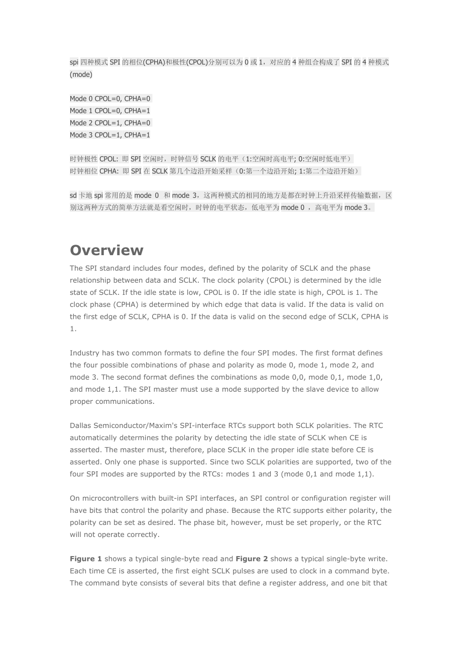
1、spi四种模式SPI的相位(CPHA)和极性(CPOL)分别可以为0或1,对应的4种组合构成了SPI的4种模式(mode) Mode 0 CPOL=0, CPHA=0 Mode 1 CPOL=0, CPHA=1 Mode 2 CPOL=1, CPHA=0 Mode 3 CPOL=1, CPHA=1 时钟极性CPOL: 即SPI空闲时,时钟信号SCLK的电平(1:空闲时高电平; 0:空闲时低电平) 时钟相位CPHA: 即SPI在SCLK第几个边沿开始采样(0:第一个边沿开始; 1:第二个边沿开始) sd卡地spi常用的是mode 0 和mode
2、3,这两种模式的相同的地方是都在时钟上升沿采样传输数据,区别这两种方式的简单方法就是看空闲时,时钟的电平状态,低电平为mode 0 ,高电平为mode 3。 Overview The SPI standard includes four modes, defined by the polarity of SCLK and the phase relationship between data and SCLK. The clock polarity (CPOL) is determined by the idle state of SCLK. If the idle state i
3、s low, CPOL is 0. If the idle state is high, CPOL is 1. The clock phase (CPHA) is determined by which edge that data is valid. If the data is valid on the first edge of SCLK, CPHA is 0. If the data is valid on the second edge of SCLK, CPHA is 1. Industry has two common formats to define the four
4、SPI modes. The first format defines the four possible combinations of phase and polarity as mode 0, mode 1, mode 2, and mode 3. The second format defines the combinations as mode 0,0, mode 0,1, mode 1,0, and mode 1,1. The SPI master must use a mode supported by the slave device to allow proper commu
5、nications. Dallas Semiconductor/Maxim's SPI-interface RTCs support both SCLK polarities. The RTC automatically determines the polarity by detecting the idle state of SCLK when CE is asserted. The master must, therefore, place SCLK in the proper idle state before CE is asserted. Only one phase
6、 is supported. Since two SCLK polarities are supported, two of the four SPI modes are supported by the RTCs: modes 1 and 3 (mode 0,1 and mode 1,1). On microcontrollers with built-in SPI interfaces, an SPI control or configuration register will have bits that control the polarity and phase. Becaus
7、e the RTC supports either polarity, the polarity can be set as desired. The phase bit, however, must be set properly, or the RTC will not operate correctly. Figure 1 shows a typical single-byte read and Figure 2 shows a typical single-byte write. Each time CE is asserted, the first eight SCLK pul
8、ses are used to clock in a command byte. The command byte consists of several bits that define a register address, and one bit that defines the data direction: a write if the next eight SCLK pulses will clock data into the part, or a read if data is clocked out of the part. Additional groups of eigh
9、t SCLK pulses continue to transfer data in the selected direction until CE is deasserted. Note: In burst mode, CE is kept high and additional SCLK cycles are sent until the end of the burst. Figure 1. Single-byte read. Note: In burst mode, CE is kept high and additional SCLK cycles are sent until the end of the burst. Figure 2. Single-byte write. Examples of SPI code are available at: Real-Time Clocks Summary The information in this application note will help ensure that SPI communication routines will function correctly.
- 温馨提示:
1: 本站所有资源如无特殊说明,都需要本地电脑安装OFFICE2007和PDF阅读器。图纸软件为CAD,CAXA,PROE,UG,SolidWorks等.压缩文件请下载最新的WinRAR软件解压。
2: 本站的文档不包含任何第三方提供的附件图纸等,如果需要附件,请联系上传者。文件的所有权益归上传用户所有。
3.本站RAR压缩包中若带图纸,网页内容里面会有图纸预览,若没有图纸预览就没有图纸。
4. 未经权益所有人同意不得将文件中的内容挪作商业或盈利用途。
5. 装配图网仅提供信息存储空间,仅对用户上传内容的表现方式做保护处理,对用户上传分享的文档内容本身不做任何修改或编辑,并不能对任何下载内容负责。
6. 下载文件中如有侵权或不适当内容,请与我们联系,我们立即纠正。
7. 本站不保证下载资源的准确性、安全性和完整性, 同时也不承担用户因使用这些下载资源对自己和他人造成任何形式的伤害或损失。
最新文档
- 踏春寻趣 乐享时光——春季旅游踏春出游活动
- 清明假期至安全不缺席风起正清明安全需守护
- 全国党员教育培训工作规划
- XX中小学公共卫生培训树立文明卫生意识养成良好卫生习惯
- 小学生常见传染病预防知识培训传染病的预防措施
- 3月18日全国爱肝日中西医结合逆转肝硬化
- 肝病健康宣教守护您的肝脏健康如何预防肝炎
- 垃圾分类小课堂教育绿色小卫士分类大行动
- 中小学班主任经验交流从胜任到优秀身为世范为人师表 立责于心履责于行
- 教师数字化转型理解与感悟教师数字化转型的策略与建议
- 团建小游戏团建破冰小游戏团队协作破冰游戏多人互动
- 教师使用deepseek使用攻略让备课效能提升
- 办公室会议纪要培训会议内容会议整理公文攥写
- 党员要注重培塑忠诚奋斗奉献的人格力量
- 橙色卡通风儿童春季趣味运动会
